WebGPU game (#11): Shadow mapping
In a previous post, I outlined how to create faux shadows using explicit shadow entities. It had a number of quirks, but kept in the spirit of the style, I think! However, for this post I want to discuss how I implemented shadow mapping. Shadow mapping is not physically accurate, either, but it is a major improvement for realtime rendering:
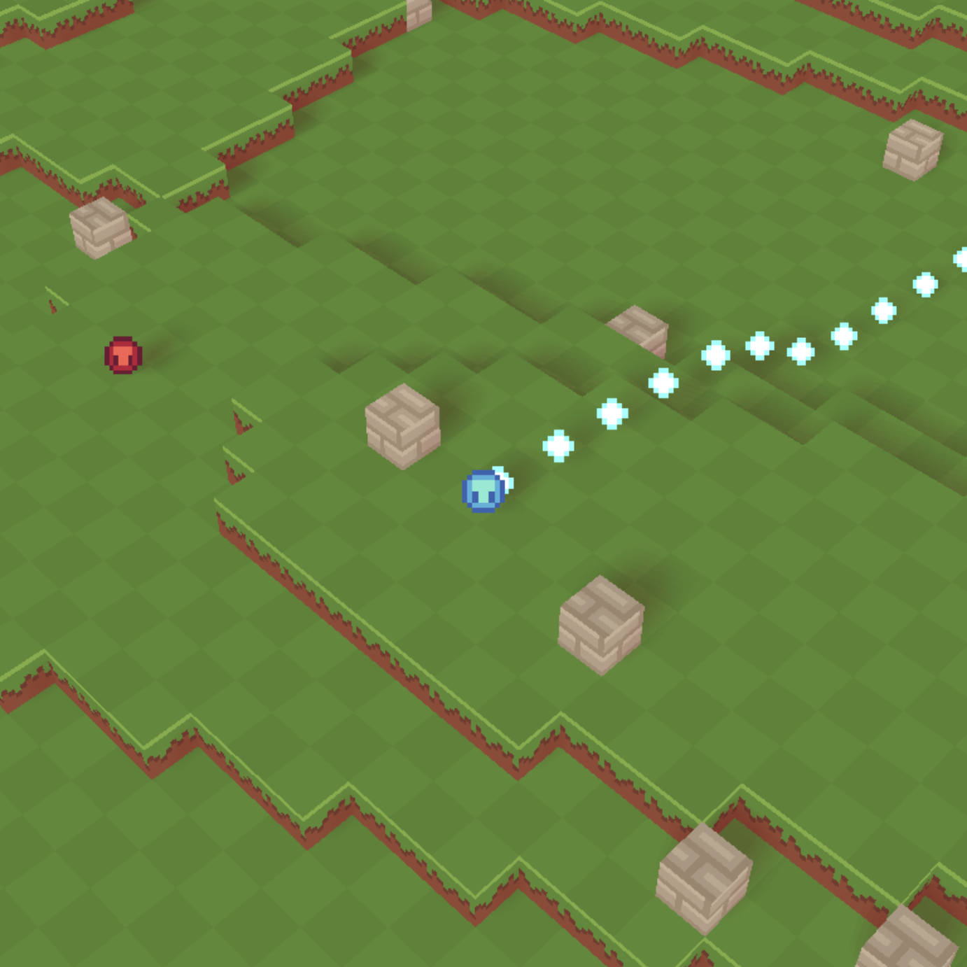
The above image clearly communicates the position of every object in the world. The previous implementation suffered from the fact that higher terrain could not be distinguished from lower terrain behind it. I opted to implement this as I think it can be good practice for bringing all the previously covered linear algebra together. All posts past #10 for this series are considered a bonus, so I won’t be covering the implementation with as much detail. You can refer to the link at the bottom of the post for the full changes.
Orthographic projection
The first change involved renaming the perspective projection and adding a new orthographic projection resource. The motivation is that I wanted to model a directional light. You can think of this as a considerably large light source that is so far away that all light emanating from it could be considered parallel. You’ll see that the matrix is identical to the one I derived in the 3D projection series.
Well, everything except the entry in the 3rd row and column. If you click through you’ll notice that I corrected the fact that the camera looks down the z-axis when constructing the perspective projection matrix. So, we simply have to do the same for the previously derived orthographic projection matrix. We multiply the orthographic matrix by another matrix which inverts the -coordinate. This maps it to left-handed clip-space. You may recognize this as a scale matrix with .
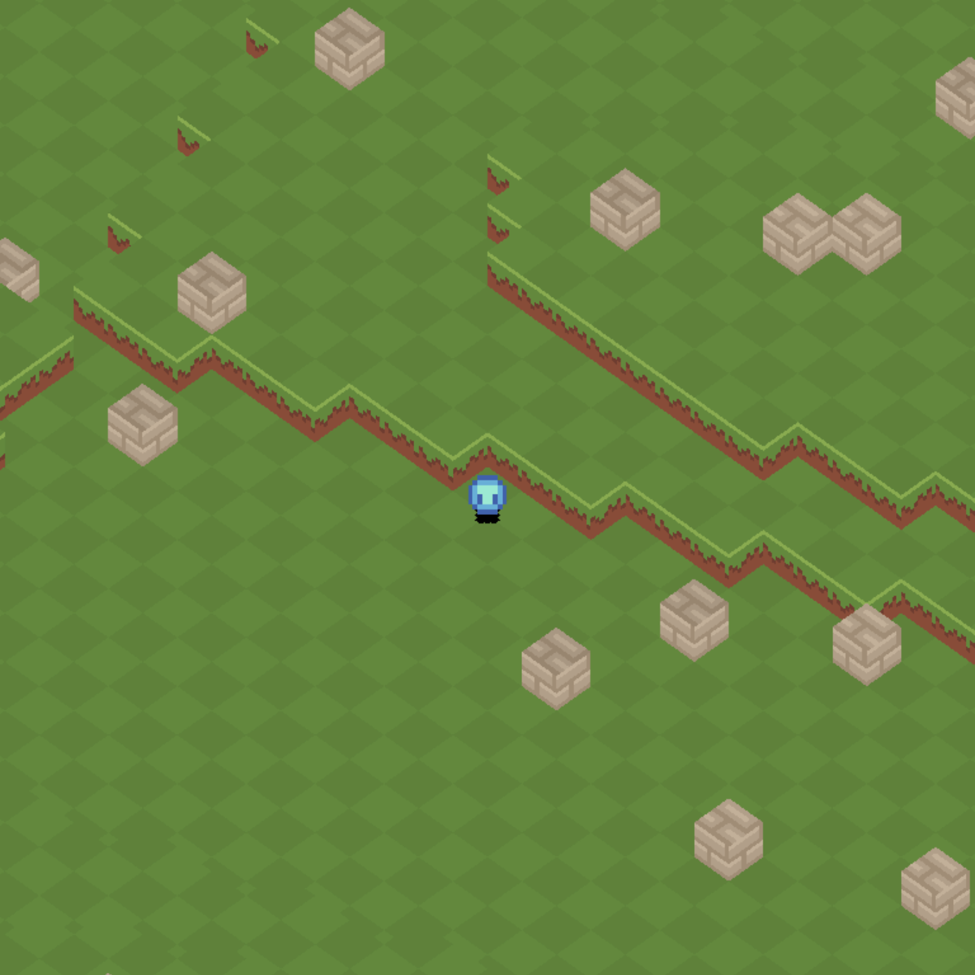
If you follow along with the diff for this change, you’ll notice that I temporarily replaced the perspective projection with the orthographic projection. I simply did this to confirm that I hadn’t made a mistake. See how every block in the scene is exactly the same relative size on the screen:
Basic shadow mapping
In the next change, I implemented some barebones shadowing mapping. The idea is to define some directional light and render the scene from the perspective of the light into a depth texture. Then, when rendering the actual scene, you calculate where your fragment would exist in light space. You will use the same “light view projection” matrix for both of these transformations.
Since you have the texture, which represents what the light can see, and this fragment in the same space, you can determine if your point is occluded by some other object by directly comparing the fragment’s -value with the value in the texture. You use the fragment’s - and -coordinates to index into the texture map to get the first point that the light “sees”1. It might be an object in front of your point or the point itself.
The majority of this change was setting up another render pipeline for the shadows. This one doesn’t need a color attachment, as we’re only interested in depth. However, I did include use the texture atlas to ensure that I could discard transparent pixels in the same way as the original shader:
// Note the return type is not needed. I forgot to drop
// this, but it doesn't really matter either way.
@fragment
fn fragmentMain(in: VertexOutput) {
  let color = textureSample(textureView, textureSampler, in.uv);
  if (color.a == 0) {
    discard;
  }
}
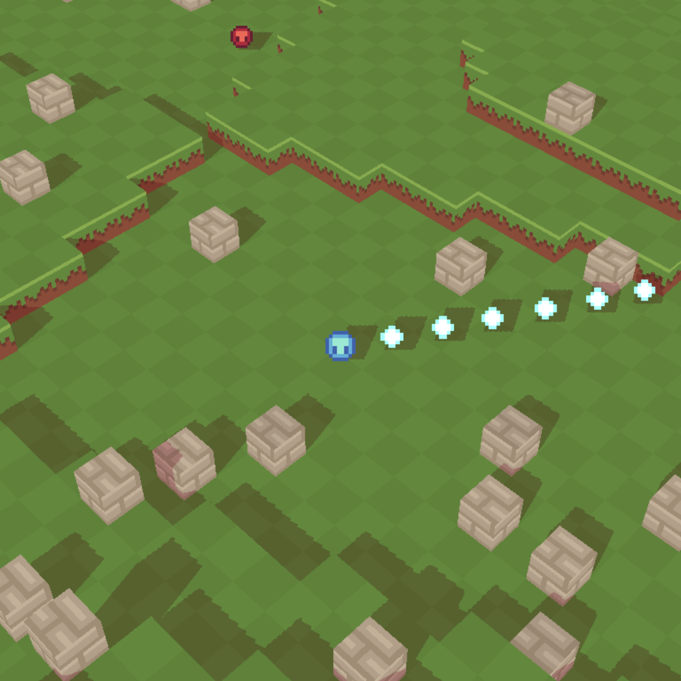
Otherwise, the entities would cast quad shadows like this:
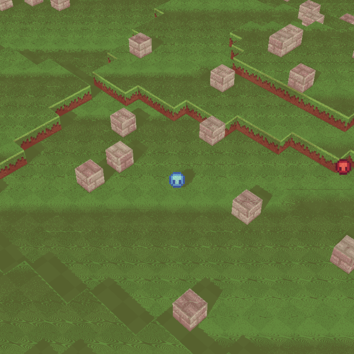
You may notice the “bias” parameter when comparing the two points. This parameter exists to resolve an issue known as “shadow acne”. This occurs as a result of the limited resolution of the shadow map. A single pixel in the map may cover more pixels in the final rendered image2. I actually didn’t see any and had an entirely blank screen at first! But, to simulate it, if we set the bias parameter too low, the following occurs:
The bias parameter can be improved by tweaking it based on the angle of the light (dot product), but I’ve chosen to hand-select one that matches the static directional light.
Percentage-closer filtering
[commit]
Percentage-closer filtering (or PCF) is a simple method for reducing the aliasing artifacts introduced by the limited size of the shadow map. I opted for this as an easy win for the appearance of the shadows. There are other strategies that are more visually pleasing and performant. Otherwise, there’s not much to discuss for this part. It’s quite a quick change to make!
Frustum-aware shadow map
[commit]
The shadow map, as implemented above, is configured by hand to follow the player and be mostly in view. When the player dies, you’ll see the shadows race off to the side. To solve this, we need to reach into our linear algebra toolkit once more. The way to do this is to determine where points on the perspective frustum will be in world-space. This would be quite painful to construct, but we can just use the inverse view projection matrix to transform the extreme points of our NDC which start at and end at into world space.
Then, we can multiply these points by the light’s view matrix. This is before the orthographic projection, so that our world units are still preserved. Then, we just go through each point finding the minimum and maximum , and values. These points directly map to the inputs of our orthographic projection, since we’re in the space that moves the orthographic cube to the origin. The only difference is that our -axis is flipped in this space, so we need to negate and swap the minimum and maximums values.
Where next?
You may have noticed, by this point, that I opted for soft and bright shadows. The reason is that the shadows would flicker and be visually pixelated if they were darker. A solution to this issue is cascading shadow maps (or CSMs). The idea is that you break up your frustum into some number of sections and render a shadow map for each section.
I’m actually happy with the really soft shadows, so I stopped before adding CSMs. There is a great article on this topic on the learnopengl website if you’re interested in tackling it. It’s not as complicated as you’d expect, but there will be a lot of rework in the pipelines and shaders to handle multiple textures.
Next time, I intend to address the absence of any actual lighting. Something like the Blinn–Phong reflection model would be sufficient for such a visually simple game.
Links
Footnotes
-
To be more accurate, the image will be mapped from 0 to 1 from the top-left. So, while they’re in the same space, you do have to map your light space coordinates from to . This also means inverting the -value, since our NDC coordinates have the -axis pointing up. ↩
-
The wonderful learnopengl shadow mapping tutorial covers this in more detail. I went through this a number of years ago before being familiar with linear algebra. I definitely felt more confident in the implementation this time around. I actually only referenced the article for the PCF part of the implementation! ↩