WebGPU game (#3): Textures and Projections
For this post, I would like to focus on getting (1) a texture mapped to a quad, and (2) the quad placed in 3-dimensional space.
Texture
I have added a very simple “programmer art”1 tileset to the repository. Feel
free to grab the tileset from the link to the Git tree below. Simply
add this file to the public folder.
Now, let’s start by writing a function to load this image into memory. Create a
file named texture.ts.
export async function webGpuTextureFromUrl(device: GPUDevice, url: string): Promise<GPUTexture> {
  const blob = await fetch(url).then(res => res.blob());
  const imageBitmap = await createImageBitmap(blob);

  const textureDescriptor: GPUTextureDescriptor = {
    label: `texture(${url})`,
    size: { width: imageBitmap.width, height: imageBitmap.height },
    usage: GPUTextureUsage.TEXTURE_BINDING |
      GPUTextureUsage.COPY_DST |
      GPUTextureUsage.RENDER_ATTACHMENT,
    format: "rgba8unorm",
  };

  const texture = device.createTexture(textureDescriptor);
  device.queue.copyExternalImageToTexture(
    { source: imageBitmap },
    { texture },
    textureDescriptor.size
  );

  return texture;
}
From the above, we’re using fetch to obtain textures, which are served from
the public directory in our project. We create a GPUTextureDescriptor which
specifies the width, height, usage and format of the texture. We then allocate
the space on our GPU for the texture with our handle to the GPUDevice. Lastly,
we submit a command to the queue to copy the bytes from our source in memory to
the GPU.
While we’re in this file, we will want to specify a helper method for determining the UV coordinates for each vertex. These are the floating-point values that range from in both the () and () axes. It’s important to note that for texture coordinates, increases to the right and increases downwards.
const TILE_SIZE = 8;
export function uvFromIndex(index: number, x: number, y: number, texture: GPUTexture): [number, number] {
  const i = ((index * TILE_SIZE) % texture.width) / texture.width;
  return [i + (x * TILE_SIZE) / texture.width, y * TILE_SIZE / texture.height];
}
We can just assume that all tiles have dimensions of 8x8, and that the texture atlas2 is just a single row. The index specifies which tile we want in the texture, while the and coordinates specify the point within that tile.
Now, in our main.ts file we load and hold onto a handle to the GPU texture. In
essence, we allow the file loaded in RAM to be cleaned up by garbage collection,
as we only need this data on the GPU.
const texture = await webGpuTextureFromUrl(device, "./tileset.png");
We need to update the vertices to define a quad and include the desired UV coordinates. I want the fourth tile (the side of the grass block), which is at index 3. Note how the first vertex, representing the bottom-left, has a UV coordinate of (0, 1).
const vertices = new Float32Array([
  // x, y, u, v
  -0.5, -0.5, ...uvFromIndex(3, 0.0, 1.0, texture),
  0.5, -0.5, ...uvFromIndex(3, 1.0, 1.0, texture),
  0.5, 0.5, ...uvFromIndex(3, 1.0, 0.0, texture),
  -0.5, 0.5, ...uvFromIndex(3, 0.0, 0.0, texture),
]);
Update the indices array to include the second triangle for the quad.
const indices = new Uint32Array([
  0, 1, 2, 0, 2, 3
]);
This has changed the structure of each vertex, so we need to update the vertex buffer layout.
const vertexBufferLayout: GPUVertexBufferLayout = {
  stepMode: "vertex",
  // new array stride, since the vertices are bigger by 8 bytes.
  arrayStride: 16,
  attributes: [
    { // pos
      format: "float32x2",
      offset: 0,
      shaderLocation: 0,
    },
    // new attribute, the UV coordinate for this vertex.
    { // uv
      format: "float32x2",
      offset: 8,
      shaderLocation: 1,
    }
  ],
};
We also need to specify a bind group layout. Bind groups are use to specify related data. These could be anything from opaque buffers, structs of primitive values, or textures.
You can also switch bind groups between compute or render passes to persist the results from previous passes and use them in the following passes. For our purposes, we will always use this one bind group for every render pass.
const bindGroupLayout = device.createBindGroupLayout({
  label: "bind group layout",
  entries: [
    {
      binding: 0,
      visibility: GPUShaderStage.FRAGMENT,
      texture: {},
    },
    {
      binding: 1,
      visibility: GPUShaderStage.FRAGMENT,
      sampler: {},
    }
  ]
});
I have specified that the first binding is a texture and the second is a sampler. You can think of the sampler as a configuration object that just indicates how to pick data from the texture. Specifically, textures are usually not sampled exactly on a pixel but somewhere between pixels. This means that there are methods for interpolating (often causing a blurry appearance at low resolutions). For our purposes, we are opting for nearest-pixel interpolation, which is essentially no interpolation.
First update the pipeline layout to include the bind group layout:
const pipelineLayout = device.createPipelineLayout({
  label: "pipeline layout",
  bindGroupLayouts: [bindGroupLayout], // updated
});
We then create the actual sampler, view and bind group. The view can be thought as some subset of the data contained within the texture. For example, mip refers to mipmaps3 which are successively scaled down versions of the original texture. These reduce noise for fragments in the distance based on sampling error without introducing an increased rendering cost. We won’t be making use of mipmaps.
const sampler = device.createSampler({
  // note that we're just grabbing the "nearest" pixel,
  // rather than interpolating
  minFilter: "nearest",
});

const view = texture.createView({
  baseMipLevel: 0,
  mipLevelCount: 1,
});

const bindGroup = device.createBindGroup({
  label: "bind group",
  layout: bindGroupLayout,
  entries: [
    {
      binding: 0,
      resource: view,
    },
    {
      binding: 1,
      resource: sampler,
    },
  ],
});
In our render pass, we must remember to actually set the bind group (as group zero):
pass.setBindGroup(0, bindGroup);
Finally, we need to update our shader to account for the new vertex attribute and the bind group. Of course, we must also include actual sampling of the texture and apply it in the fragment shader.
First, the new UV attribute:
struct VertexInput {
  @location(0) pos: vec2f,
  @location(1) uv: vec2f, // new
};

struct VertexOutput {
  @builtin(position) clip_pos: vec4f,
  @location(0) uv: vec2f, // new
};
Next, we specify the bindings for our bind group – the texture view and sampler.
@group(0) @binding(0) var textureView: texture_2d<f32>;
@group(0) @binding(1) var textureSampler: sampler;
We can replace the vertex shader for the rainbow triangle with the following. Right now, nothing special is happening in the vertex shader. We’re essentially just passing through the inputs to the fragment shader after rephrasing the input position (2D) as a clip space position (4D).
@vertex
fn vertexMain(in: VertexInput) -> VertexOutput {
  var output: VertexOutput;
  output.clip_pos = vec4f(in.pos, 0, 1);
  output.uv = in.uv;
  return output;
}
We then use the builtin textureSample function4 which grabs the nearest value
of the input texture at the given floating-point coordinate.
@fragment
fn fragmentMain(in: VertexOutput) -> @location(0) vec4f {
  let color = textureSample(textureView, textureSampler, in.uv);
  return vec4(color);
}
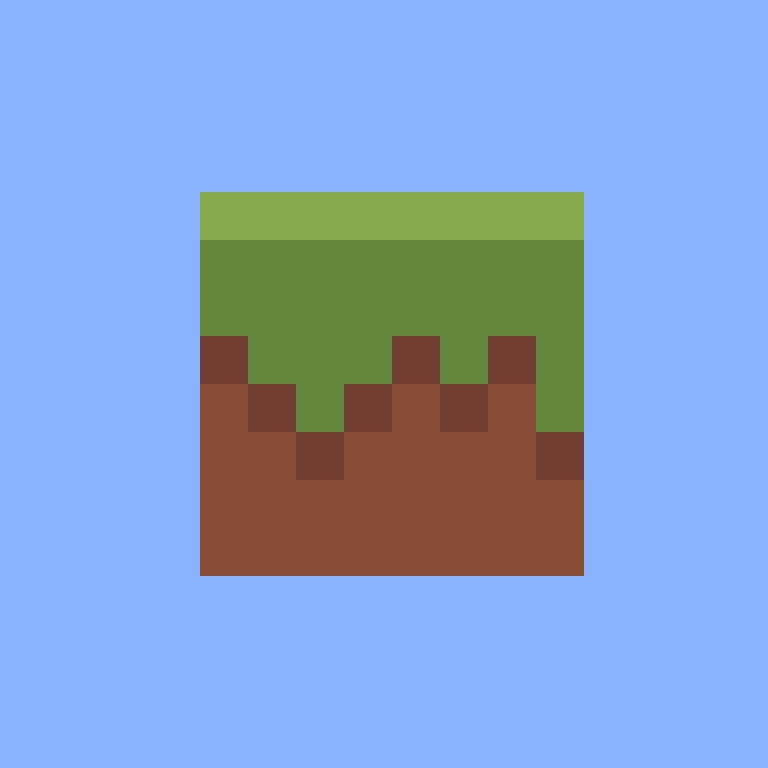
You should end up with the following result:
Projections
I thought I would squeeze the projection work into this post, since the texture additions were quite minimal. If you haven’t, or you’re not comfortable with the MVP transformation matrix, I’d recommend going through my 3D projection series. I won’t be explaining the why of the matrices I use here. You can really think of matrices as compressed maths operations, which means that they are explicitly hard to interpret just through observation (at least for this mere mortal).
Maths module
We’re going to need some basic data types for representing common mathematical
constructs. I have opted to create a math directory. Inside this directory
we’ll need a vec3.ts, vec4.ts and mat4.ts file.
For vec3.ts, we need the following:
/**
 * A 3-dimensional vector.
 */
export class Vec3 {
  /**
   * Internal representation of the vector components.
   */
  rep: [number, number, number];

  constructor(x: number, y: number, z: number) {
    this.rep = [x, y, z];
  }

  get x() {
    return this.rep[0];
  }

  get y() {
    return this.rep[1];
  }

  get z() {
    return this.rep[2];
  }

  set x(value: number) {
    this.rep[0] = value;
  }

  set y(value: number) {
    this.rep[1] = value;
  }

  set z(value: number) {
    this.rep[2] = value;
  }

  dot(other: Vec3): number {
    return this.x * other.x + this.y * other.y + this.z * other.z;
  }

  cross(other: Vec3): Vec3 {
    return new Vec3(
      this.y * other.z - this.z * other.y,
      this.z * other.x - this.x * other.z,
      this.x * other.y - this.y * other.x
    );
  }
}
I use the array representation internally so that I can use indexing operations, since I don’t think JavaScript has support for operator overloading on the index operation. Otherwise, the most important part of this implementation are the dot and cross products. These are used extensively in the derivation of the view matrix.
I’ll omit the Vec4 implementation, but it’s essentially the same minus the
cross product. I’ve named the fourth component w.
Lastly, for the math module, we have the matrix implementation:
import {Vec4} from "./vec4";

/**
 * A 4x4 square matrix.
 */
export class Mat4 {
  rows: [Vec4, Vec4, Vec4, Vec4];

  constructor(
    r0c0: number, r0c1: number, r0c2: number, r0c3: number,
    r1c0: number, r1c1: number, r1c2: number, r1c3: number,
    r2c0: number, r2c1: number, r2c2: number, r2c3: number,
    r3c0: number, r3c1: number, r3c2: number, r3c3: number,
  ) {
    this.rows = [
      new Vec4(r0c0, r0c1, r0c2, r0c3),
      new Vec4(r1c0, r1c1, r1c2, r1c3),
      new Vec4(r2c0, r2c1, r2c2, r2c3),
      new Vec4(r3c0, r3c1, r3c2, r3c3),
    ];
  }

  row(index: number): Vec4 {
    return this.rows[index];
  }

  column(index: number): Vec4 {
    return new Vec4(
      this.rows[0].rep[index],
      this.rows[1].rep[index],
      this.rows[2].rep[index],
      this.rows[3].rep[index],
    );
  }

  /**
   * Converts this matrix into a column-major buffer for WebGPU.
   */
  buffer(): Float32Array {
    return new Float32Array([
      ...this.column(0).rep,
      ...this.column(1).rep,
      ...this.column(2).rep,
      ...this.column(3).rep,
    ]);
  }

  mul(other: Mat4): Mat4 {
      const result = Mat4.zero();
      for (let i = 0; i < 4; i++) {
        for (let j = 0; j < 4; j++) {
          result.rows[i].rep[j] = this.row(i).dot(other.column(j));
        }
      }

      return result;
  }

  static zero(): Mat4 {
    return new Mat4(
      0, 0, 0, 0,
      0, 0, 0, 0,
      0, 0, 0, 0,
      0, 0, 0, 0,
    );
  }
}
There’s a lot inside this implementation but to cover the basics:
- I use a row-major format, so the method for creating a buffer for WebGPU needs to convert the output to a column-major format.
- There is a matrix multiplication method. Since we store our matrix as vectors, we can use the definition of the dot product for an implementation that closely resembles the definition of matrix multiplication.
- I have added a static method for returning a zero matrix, for convenience. I may even recommend adding an identity method, too. I often use that for debugging matrix composition issues.
View projection
Create a file called camera.ts at the top level of your source directory. I’ve
added comments inline with the implementation, but feel free to omit these.
import {Mat4} from "./math/mat4";
import {Vec3} from "./math/vec3";

export class Camera {
  position: Vec3;
  yaw: number;
  private _pitch: number;

  constructor(position: Vec3) {
    this.position = position;
    this.yaw = 0;
    this._pitch = 0;
  }

  get pitch() {
    return this._pitch;
  }

  /**
   * Set the pitch between -90 and 90 degrees. Anything else is disregarded as
   * we treat y as up.
   */
  set pitch(value: number) {
    this._pitch = Math.max(-Math.PI/2 + 0.01, Math.min(Math.PI/2 - 0.01, value));
  }

  /**
   * Our view matrix, as derived in the 3D projection series.
   */
  matrix(): Mat4 {
    const e = this.position;
    const d = this.dir();
    const r = d.cross(new Vec3(0, 1, 0));
    const u = r.cross(d);
    return new Mat4(
       r.x,  r.y,  r.z, -e.dot(r),
       u.x,  u.y,  u.z, -e.dot(u),
      -d.x, -d.y, -d.z,  e.dot(d),
         0,    0,    0,         1
    );
  }

  /**
   * For illustration, you don't need this. This is a naive implementation for
   * "right" because, based on our derivations, the dir, right and up vectors
   * must be orthogonal.
   */
  right(): Vec3 {
    return new Vec3(Math.cos(this.yaw), 0.0, -Math.sin(this.yaw));
  }

  /**
   * A slightly unconventional direction matrix. I assume a yaw of zero faces
   * negative z. I've more commonly seen it face positive x in other
   * implementations. I've kept the convention that a positive yaw rotates
   * counter-clockwise.
   */
  dir(): Vec3 {
    const xzLength = Math.cos(this.pitch);
    return new Vec3(
      -xzLength * Math.sin(this.yaw),
      Math.sin(this.pitch),
      -xzLength * Math.cos(this.yaw),
    );
  }
}
Create another file called projection.ts. This is our perspective projection
as derived in the 3D projection series. There is not much else to this class!
You could also cache the matrix result internally and only change it whenever
one of the parameters change using setters, as the projection does not often
change every frame for most applications.
import {Mat4} from "./math/mat4";

export class Projection {
  width: number;
  height: number;
  fovY: number;
  near: number;
  far: number;

  constructor(
    width: number,
    height: number,
    fovYRadians: number,
    near: number,
    far: number
  ) {
    this.width = width;
    this.height = height;
    this.fovY = fovYRadians;
    this.near = near;
    this.far = far;
  }

  matrix(): Mat4 {
    let perspMatrix = Mat4.zero();
    const aspect = this.width / this.height;
    const tan = Math.tan(this.fovY / 2);
    perspMatrix.rows[0].x = 1 / (aspect * tan);
    perspMatrix.rows[1].y = 1 / tan;
    perspMatrix.rows[2].z = this.far / (this.near - this.far);
    perspMatrix.rows[2].w = this.far * this.near / (this.near - this.far);
    perspMatrix.rows[3].z = -1;
    return perspMatrix;
  }
}
For convenience, I’ve also created a file for static configuration called
config.ts and I’ve added the following two constants:
export const SCREEN_WIDTH = 768;
export const SCREEN_HEIGHT = 768;
This is just so that I can authoritatively manage and reference the width and height in once place. I’ve removed the width and height from the canvas in the HTML.
At the last stretch, we move to the main.ts file. First, set the canvas width
and height using our new static config variables.
canvas.width = SCREEN_WIDTH;
canvas.height = SCREEN_HEIGHT;
We can add the coordinate to our quad, but just set it to zero for now. This also means we must update the vertex buffer layout:
const vertices = new Float32Array([
  // x, y, z, u, v
  -0.5, -0.5, 0, ...uvFromIndex(3, 0.0, 1.0, texture),
  0.5, -0.5, 0, ...uvFromIndex(3, 1.0, 1.0, texture),
  0.5, 0.5, 0, ...uvFromIndex(3, 1.0, 0.0, texture),
  -0.5, 0.5, 0, ...uvFromIndex(3, 0.0, 0.0, texture),
]);

...

const vertexBufferLayout: GPUVertexBufferLayout = {
  stepMode: "vertex",
  arrayStride: 20, // updated
  attributes: [
    { // pos
      format: "float32x3", // updated
      offset: 0,
      shaderLocation: 0,
    },
    { // uv
      format: "float32x2",
      offset: 12, // updated
      shaderLocation: 1,
    }
  ],
};
We’re going to want to specify a new buffer inside of our bind group layout. This is called a uniform, which is essentially a value that is the same (or uniform) across an entire render pass. Our view and projection matrices are great candidates for this, as each vertex needs this information.
...
{
  binding: 2,
  visibility: GPUShaderStage.VERTEX | GPUShaderStage.FRAGMENT,
  buffer: {
    type: "uniform"
},
...
Just above our bind group, itself, we’re going to want to calculate the view and projection matrices (compressed into one) and write that out as the contents of our new uniform buffer.
// place the camera at z=5 (it's looking down -z)
const camera = new Camera(new Vec3(0, 0, 5));
const projection = new Projection(
  SCREEN_WIDTH,
  SCREEN_HEIGHT,
  // choose a very small FOV to have a near-isometric look
  toRadians(35),
  0.1,
  500
);
// pre-multiply our view and projection matrices once before rendering
// this avoids the need to do the same multiplication for every vertex!
const viewProj = projection.matrix().mul(camera.matrix());

// Create a uniform buffer using the [Mat4] buffer method.
const uniformsArray = viewProj.buffer();
const uniformsBuffer = device.createBuffer({
  label: "uniforms buffer",
  size: uniformsArray.byteLength,
  usage: GPUBufferUsage.UNIFORM | GPUBufferUsage.COPY_DST,
});
device.queue.writeBuffer(uniformsBuffer, 0, uniformsArray);
You’ll notice the toRadians method. I’ve created a helpers.ts file in the
math directory for some common methods.
export function toRadians(degrees: number) {
  return degrees * Math.PI / 180;
}
Now, add the uniform buffer to our bind group:
...
{
  binding: 2,
  resource: {buffer: uniformsBuffer},
}
...
Now, our last step is to wire this all together in the shader. First, update the position to include the new -coordinate.
@location(0) pos: vec3f,
Define a struct to represent our uniform values:
struct Uniforms {
  viewProj: mat4x4f,
};
Add the binding for our bind group:
@group(0) @binding(2) var<uniform> uniforms: Uniforms;
And finally, multiply the view projection matrix by our vertex position:
output.clip_pos = uniforms.viewProj * vec4f(in.pos.xyz, 1);
You may have noticed that I’ve omitted the model matrix. We’ll add that in a follow up post, but this is sufficient for presenting the projection.
Confirmation
You may not find the above satisfactory in terms of correctness. You could definitely throw these values into some unit & fuzz tests to ensure the edge cases are handled, but for my purposes I’ve just played around with various configurations.
For example, try and modify the screen width – lie and say it’s half the size for your projection. Notice how the image stretches as if targeted for a thinner canvas.
I made a follow up commit just to test the projection in an animated fashion. It’s worth following along, as I’ll keep some of this machinery until the end. First, I moved the render pass into an animation frame:
function eventLoop() {
    // entire render pass here

    requestAnimationFrame(eventLoop);
}

// kick off the render loop
requestAnimationFrame(eventLoop);
This just ensures that the render loop is called at about the same rate as your screen’s refresh rate. There’s no real reason to go much faster than that, other than making a warm box or reducing battery life in some sort of odd competition.
Now, for the preamble to the event loop, I’ve added the following:
const now = performance.now();
// how far the camera is from its target
const radius = 5;
// an angle that changes at a rate of about a radian per second.
const angle = now / 1000;
// start the camera at z=5, x=0 looking down the negative z.
// confirm this makes sense by working in 90 degree increments.
camera.position.x = Math.sin(angle) * radius;
camera.position.z = Math.cos(angle) * radius;
camera.yaw = angle;
// vary the FOV at half the rate of the camera's yaw
projection.fovY = toRadians(60 + (30 * Math.cos(now / 2000)));

// submit the new view-projection matrix
const viewProj = projection.matrix().mul(camera.matrix());
const uniformsArray = viewProj.buffer();
device.queue.writeBuffer(uniformsBuffer, 0, uniformsArray);
This exercises a few of the values we have available to modify the projection. You should end up with the following animation. The camera is moving counter-clockwise around the quad, and its FOV is changing (giving the appearance that the camera is moving back and forth).
Links
Footnotes
-
WebGPU also has support for texture arrays which I have not fully explored yet. https://en.wikipedia.org/wiki/Texture_atlas ↩
-
This and more builtin functions are specified in the WebGPU W3C working draft: https://www.w3.org/TR/WGSL/#texturesample ↩