WebGPU game (#2): Rainbow triangle
Today, I just want to get something rendering on the screen. This requires quite a bit of boilerplate (more), and next is some linear algebra for projecting 3D objects onto the screen. I’m going to split out the proofs for these transformation matrices into separate posts, as they helped me understand the bigger picture. However, they will not be required reading for working through this project.
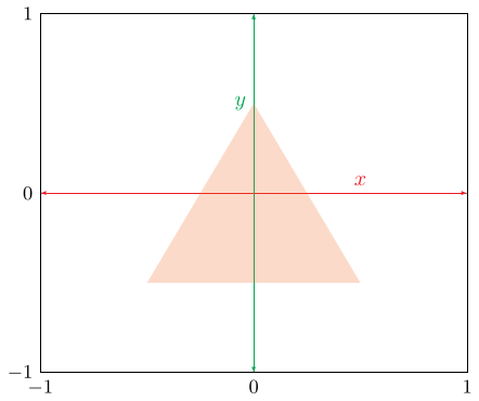
Let’s get started with rendering a triangle to the screen! First, we want to define some vertices for the triangle in two-dimensions.
// main.ts (after context.configure({...});)
const vertices = new Float32Array([
   // x, y
   -0.5, -0.5,
   0.5, -0.5,
   0.0, 0.5,
]);
This represents a triangle drawn in the center of the screen, which is mapped from [-1, 1] on both the x- and y-axes. Note that this means that the final output does not consider screen dimensions and will stretch if you change the dimensions of the canvas.
Next, we need to send this data over to the graphics card. We do this by
creating a buffer via the GPUDevice. We specify the length of this buffer via
the byte length of the buffer created above. Then, we write from the buffer in
memory to the graphics card via the queue. Note that we have to mark the buffer
as COPY_DST1 to write any data into the buffer via the queue.
// main.ts
const vertexBuffer = device.createBuffer({
  label: "vertex buffer",
  size: vertices.buffer.byteLength,
  usage: GPUBufferUsage.VERTEX | GPUBufferUsage.COPY_DST
});

device.queue.writeBuffer(vertexBuffer, 0, vertices);
We now need to define the vertex buffer layout. We specify the stepMode as
“vertex” – the alternative option will be discussed later. Then, we define the
arrayStride which is the number of bytes between logical groupings of
vertices. In our case, we have two 32 bit floats (or bytes) to
represent the x and y coordinates. Then, in attributes we specify the logical
sub-groupings of the vertex – you can store more than positional information in
a vertex. The shaderLocation will be referenced next.
const vertexBufferLayout: GPUVertexBufferLayout = {
  stepMode: "vertex",
  arrayStride: 8,
  attributes: [{
    format: "float32x2",
    offset: 0,
    shaderLocation: 0,
  }],
};
In our src directory, we’re going to add a shader.wgsl file. This allows us
to programmatically specify how vertices are interpreted and eventually drawn to
the screen. This is managed through two functions specified as the vertex shader
and fragment shader. You can think of the fragment shader as a “pixel” shader.
First, we’ll define two data types: VertexInput and VertexOutput. The input
has the vertex position (specified as shaderLocation above) and a builtin
value for vertex inputs2. These builtins are always available and don’t have
to be specified in your render pipeline definitions.
// shader.wgsl
struct VertexInput {
  @location(0) pos: vec2f,
  @builtin(vertex_index) index: u32,
};
The output must produce the position builtin, which is used for clipping
triangles outside of the view and as a mandatory input to the fragment shader. I
have additionally specified a 3-vector to tint the colour of the vertex.
// shader.wgsl
struct VertexOutput {
  @builtin(position) clip_pos: vec4f,
  @location(0) tint: vec3f,
};
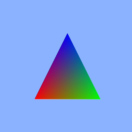
Next we’ll define the vertex shader by tagging it with a @vertex attribute.
This function just interprets a boolean value comparing the index to a specific
value and casting it as a float. The version I have in my commit history is
embarrassingly more complicated!
// shader.wgsl
@vertex
fn vertexMain(in: VertexInput) -> VertexOutput {
  var output: VertexOutput;
  let i = in.index;
  let r = f32(i == 0);
  let g = f32(i == 1);
  let b = f32(i == 2);
  output.clip_pos = vec4(in.pos, 0, 1);
  output.tint = vec3(r, g, b);
  return output;
}
Now, we just output the tint calculated by the vertex shader by grabbing the
VertexOutput as the input to the fragment shader. The location at the end of
this shader relates to the index of the targets array in the pipeline
definition below. Just know that we’ll only be using one (the texture for the
canvas).
// shader.wgsl
@fragment
fn fragmentMain(in: VertexOutput) -> @location(0) vec4f {
  return vec4(in.tint, 1.0);
}
Finally, returning to the main.ts file, we import the shader source as a
string by using a nifty Vite feature3 which allows you to compile the source
of a separate file into your own. Since we are not producing shaders at runtime,
this saves us an async fetch at runtime.
Then, we build a shader module by sending it to be compiled for the GPU.
// main.ts
import shaderSource from "./shader.wgsl?raw";

...

const shaderModule = device.createShaderModule({
  label: "shader module",
  code: shaderSource,
});
At the final stretch, we generate our render pipeline. Right now, we have no
bind groups so the layout is quite bare. Then we create the pipeline by
specifying the names of the vertex and fragment shader functions. Additionally,
we provide the vertexBufferLayout (partial version of the VertexInput
specified in the shader, excluding builtins) and the targets for the fragment
shader. In this case, just the one – the canvas.
// main.ts
const pipelineLayout = device.createPipelineLayout({
  label: "pipeline layout",
  bindGroupLayouts: [],
});

const pipeline = device.createRenderPipeline({
  vertex: {
    module: shaderModule,
    entryPoint: "vertexMain",
    buffers: [vertexBufferLayout],
  },
  fragment: {
    module: shaderModule,
    entryPoint: "fragmentMain",
    targets: [{format: canvasFormat}]
  },
  layout: pipelineLayout,
});
We then just have to set the pipeline, pass in the handle to the vertex buffer
and initiate a draw command by specifying the number of vertices to draw. Since
our vertices array has 2 attributes per vertex, we just divide the length by
2.
// main.ts
pass.setPipeline(pipeline);
pass.setVertexBuffer(0, vertexBuffer);
pass.draw(vertices.length / 2);
But my vertices are going to get big
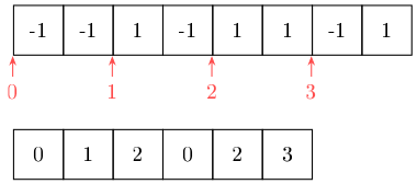
Right now, we’re only drawing a triangle, but I generally want to work with quads/rectangles. This means, using our triangle primitive, we’d need to specify 6 vertices per quad. Alternatively, we could specify 4 vertices and then a buffer representing the triangles as a series of indexes into the vertex array. This tiny saving may seem useless at first, but as we decorate a vertex with more data – the index stays at exactly 4 bytes.
Consider the example for a quad below, we have the vertex and index buffers, respectively. As soon as we add a third dimension, this index would break even on byte cost. However, we are going to add more information to each vertex moving forward.
We define another buffer, but marking it as a u32 array.
// main.ts
const indices = new Uint32Array([
  // simply indexing the first, second and third vertices by 0-index
  0, 1, 2,
]);

const indexBuffer = device.createBuffer({
  label: "index buffer",
  size: indices.buffer.byteLength,
  usage: GPUBufferUsage.INDEX | GPUBufferUsage.COPY_DST,
});

device.queue.writeBuffer(indexBuffer, 0, indices);
Then, we simply set the index buffer after the vertex buffer and use a
drawIndexed call. The second parameter can be used for instanced rendering,
which is beyond the scope of this project. But, simply, instanced rendering
allows you to specify a number of identical objects to render to the screen. It
is generally much more performant when rendering a large number of objects.
// main.ts
pass.setIndexBuffer(indexBuffer, "uint32");
pass.drawIndexed(indices.length, 1);
Links
Footnotes
-
For more buffer usage flags and their definitions: https://developer.mozilla.org/en-US/docs/Web/API/GPUBuffer/usage ↩
-
For more builtins: https://www.w3.org/TR/WGSL/#builtin-values ↩
-
Vite documentation on importing assets as strings: https://vitejs.dev/guide/assets.html#importing-asset-as-string ↩